How I converted my Logitech G29 into a rudder system using the Pi Pico
Join me on a DIY journey as I turn my Logitech G29 pedals into a flight simulator rudder system. Experience the excitement and challenges I faced creating this adaptable, cost-effective setup

purpose
I enjoy playing flight simulators and, during the build process for this adapter (June 2022) I was reeeaaaally into DCS World and MSFS 2020. Both of which, heavily rely on a rudder axis. I have a HOTAS system and the Honeycomb Alpha and Bravo peripherals, which are great. But I don't, however, have any "professional" rudder pedals.
In my eyes I couldn't justify spending $200-$300 CAD on a device that closely resembles my pedal system on my Logitech G29. Another issue is that my place is small and I'm already lacking space to store the devices I have now, let alone a separate rudder system.
Consequently, I experimented with having both my G29 and my flight sim stuff plugged in while playing MSFS2020. I utilized VJoy on my Windows PC to create a new virtual gamepad with an axis that combine the Logitech's clutch and throttle pedals to simulate an airplane's rudder. It functioned surprisingly well, save for the necessity of having this enormous steering wheel also connected to my PC and mounted to my desk.
I began searching for solutions online and discovered a video by amstudio where they used an Arduino Leonardo as an adapter to use the Logitech pedals as a standalone device.
requirements
- A Logitech G29 (I think the G25, G27, and G920 would also work) pedals
- DB9 female connectors
- Raspberry Pi Pico
- some soldering skills
build log
The first step in building this adapter involved sourcing the parts. I conducted research on the type of connector required to link to the pedal cord (it essentially looks like a miniature VGA connector).
Thanks to the video mentioned above, I found an eBay seller offering a bulk pack of DB9 connectors. I needed just one, but other sellers who only sold one piece had their prices jacked up.
The next crucial component was getting the microcontroller which would serve as the brains for the adapter. I settled on the Raspberry Pi Pico as I'm familiar with the Raspberry Pi ecosystem and they also have a lot of horsepower for the price. I bought a pack of 3 Pi Picos for $12 CAD. The extra two would serve as backups, but I also intend to construct more complex systems in the future, should any of the other Picos survive.
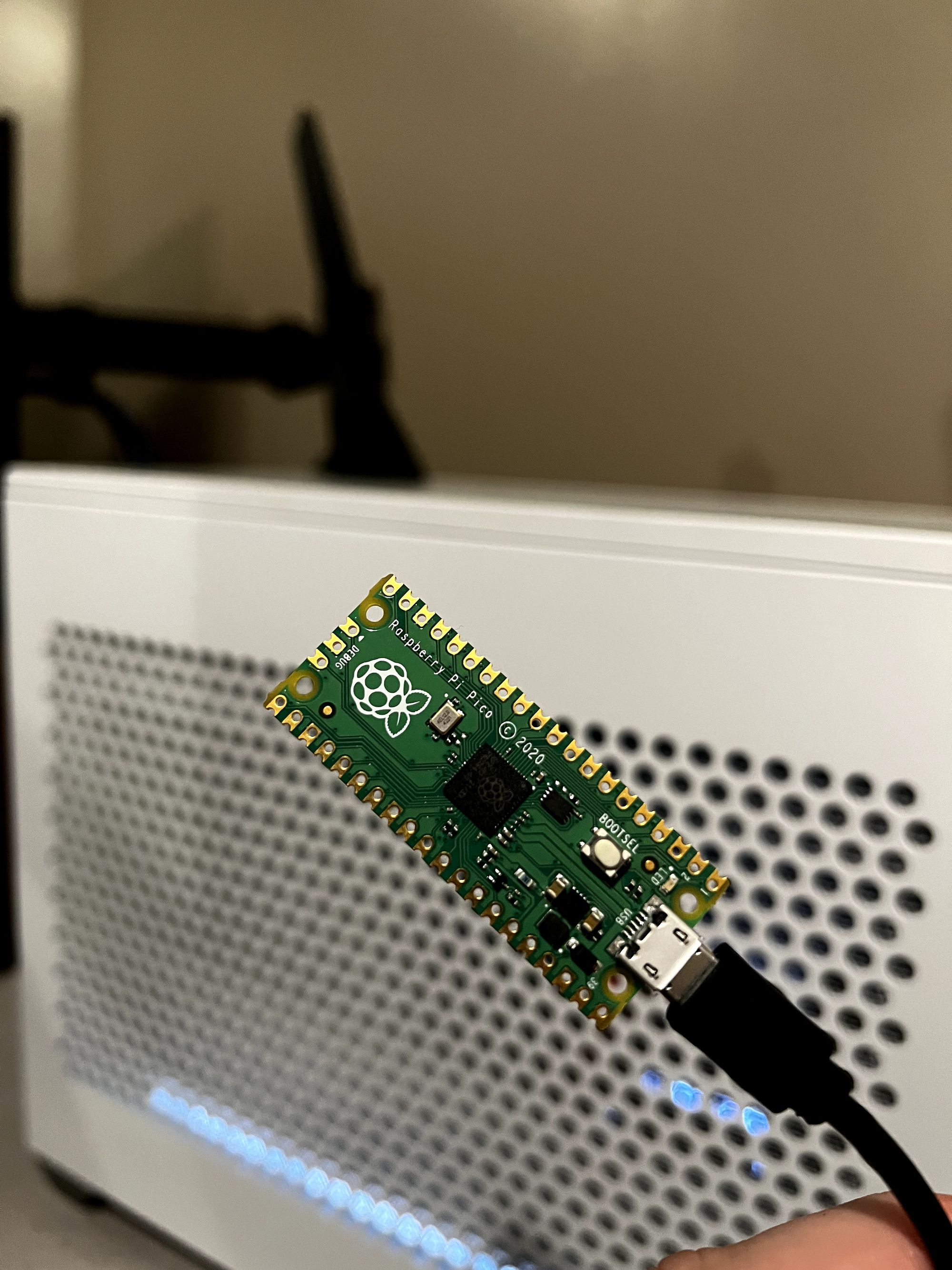
The first thing you do with any microcontroller is to run the classic "blink" program to verify the device and all the connection are functional. Once the firmware and the program were flashed onto the device and I saw the reassuring blink of a light, it was time to tackle the most challenging part of the project.
Now, I've soldered a few things in my life but nothing of this size... The footprint of the Pi Pico is close to the size of my thumb, with thepin holes being significantly smaller. I was too budget-conscious (and perhaps too proud) to buy the pre-soldered Picos with pin headers on PiShop. Buying the stock Picos also gave me an excuse to practice my soldering skills.
All things considered, the soldiering was fairly straightforward; the primary challenge was ensuring the correct pins from the DB9 connecter were soldered to the correct location on the Pico.
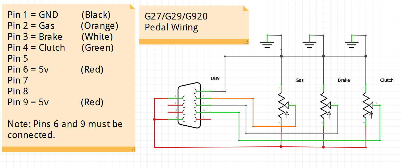
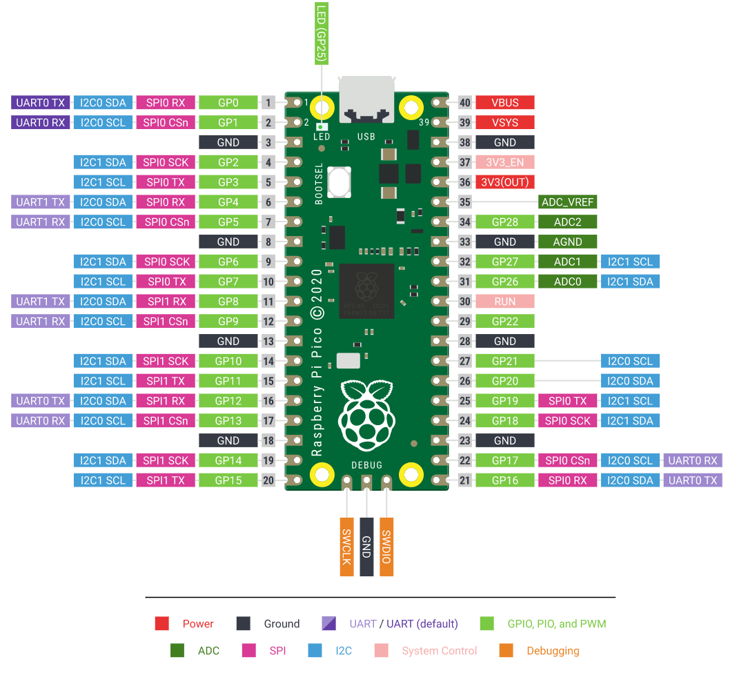
Fortunately, not all 9 pins of the DB9 had to be soldered – only the core pins needed to be, which were the input potentiometers (Orange, White, and Green in the diagram), ground (Black), and the power pins (Red). One caveat is that the diagram above uses 5v for the power pins, but the Pico does not have a 5v pin, so I utilized the 3v3 pin instead. The ground was, predictably, wired to the ground pin on the Pico. The input potentiometers were wired to the analog inputs (ADC0, ADC1, and ADC2) of the Pico.
And with all that said...
It's Alive!!!
Now that the difficult part was completed, the rest of the project was smooth sailing. Well.... kinda. One of the reasons I chose the Pi Pico is because it can act as a USB HID device, meaning that you can trick the computer into thinking that the Pico is a keyboard, mouse, gamepad, etc.
For the purposes of this project, I wanted the Pico to behave as a game controller so that it would be recognized in my games with the correct axis. To do this I utilized the PicoGamepad library which handles all the heavy lifting in terms of HID emulation and providing a user-friendly interface to send inputs to the virtual gamepad.
input mapping
The whole purpose of this project was to adapt the Logitech pedal input to be used as a flight simulator rudder input. Which means that the next logical step for the project is to implement that remapping.
The rudder remapping was fairly simple to implement – essentially, you combine both the clutch and throttle axis to create a single "rudder" axis. So when both pedals are in their starting position, the output is 50%. Pressing the clutch moves the output towards 0%, and pressing the throttle moves it towards 100%. Pressing both pedals cancels out the input and gives an output of 50%. Here's a little video demo:
One issue I came upon was that the potentiometer output for each pedal does not precisely map 0 to 1024 (the precision of each pedal). Depending on wear, manufacturing defects, or other factors, some pedals cannot output the full range of values. Also, the brake has a pretty tough spring, meaning that you cannot fully depress the pedal. So, for these reasons we need to build a system that can dynamically "remap" the specific min/max of each pedal into the 0 to 1024 range our code is expecting.
I stumbled upon an implementation from a similar project for Arduino that stores the min/max for each pedal when the device is first connected, and it uses this min/max to remap the output to the full range expected by the code. However, this means that each time you use the device or restart your PC, you need to depress each pedal to their maximum to calibrate the mapping in the code.
One clear future upgrade would be to store these pedal min/max values in some sort of long-term storage to eliminate the need for calibration each time you use the adapter. It would also be beneficial to establish some sort of dead zone calibration in the software to prevent erratic inputs.
Another upgrade would involve adding a button to swap the pedal system from flight sim mode back into racing mode.
project code
Link to the GitHub project: pico-logi-pedals
future plans
Well, when I initially planned this project a year ago, I wanted to implement this project in Rust using the pi-pico rust crate. I ran into some weird HID emulation issue, so I decided to used C++ for convenience. If I have more time in the future, I'd like to rewrite this code in Rust for fun (and for practice, I guess).
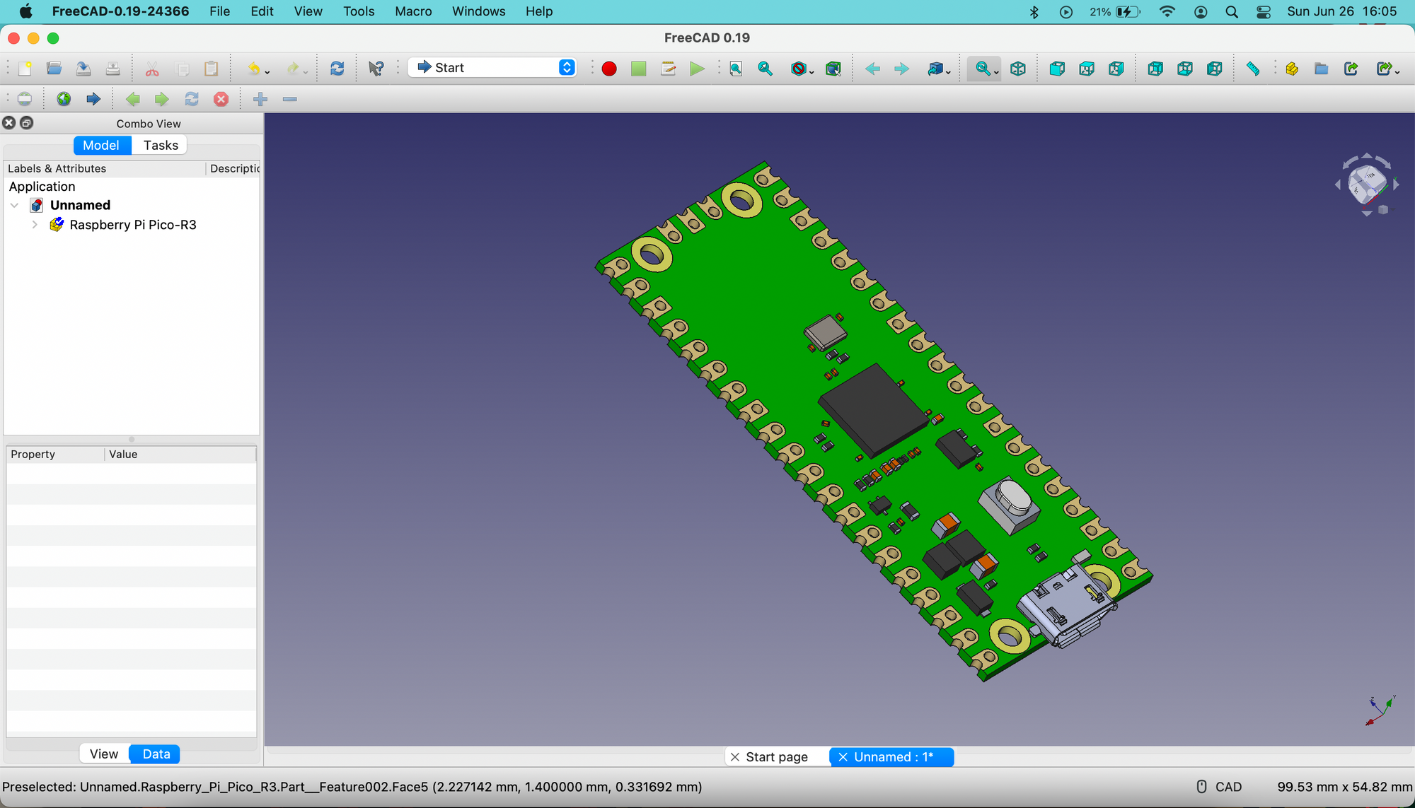
Also, I would like to 3D print a case for the adapter. I'm not going to sugarcoat it, the device looks pretty ugly with the exposed circuit board and wires (which are waaay too long). Before I do that I need to learn how to design objects in FreeCAD, but that's a project for a later time.